Strain Gauges
The LTT24 provides optional inputs for strain gauges.
1/4, 1/2 and full bridges are supported.
Adjustable sensor supply: 1, 2, 5, 10V (maximum 1W per channel.)
Internal extra resistors: 120 and 350 Ohm.
Sense line
ICP Sensors
The LTT24 provides optional inputs for ICP sensors.
Accelerometers, pressure sensors, measurement microphones and many others can be connected.
Constant current can be selected between 0.5mA and 10mA in 0.5mA steps.
Charge Sensors
The LTT24 provides optional inputs for charge sensors.
Pressure sensors, hydrophones and many others can be connected.
Measuring range: +/- 5nC
Sensitivity: 1mV/pC
High-pass 150mHz, 1,5Hz and 15Hz
Automatic and manual discharging of the capacity.
Voltage and Current Inputs
The LTT24 offers voltage and current inputs.
Measuring ranges +/-250mV, 5V, 50V and optionally 200V.
Plus +/-50mA
24bit A/D converter.
Sample frequency: up to 4MSample/s per channel
Bandwidth: DC - 1,7MHz
Very low noise: -100dB to FSR at 1MHz
![]() 16bit ENOB (Effective number of bits)
16bit ENOB (Effective number of bits)
More information: r_435
Pulse Input
The LTT24 provides optional inputs for pulse signals.
Each Pulse Module has up to 3 inputs (A, B, Z) that are sampled with 1.024GHz.
Input range -30…+80V with digitally adjustable trigger threshold.
A: Pulse input (sinusoidal or TTL)
B: Direction of rotation (for example cosine)
Z: 0° identification. One pulse per revolution.
Internal calculation of φ angle and its time derivatives φ' und φ''.
Plus ∆φ and ∆φ' and ∆φ'' for a virtual uniformly rotating system.
Analogue output of one mathematical result per Pulse Module.
Output amplitude circa ±5V Possible applications:
Tip Timing on turbines
Rotational vibration analysis
The analogue outputs can for example be used to connect a FFT Analyser and to analyse the ∆φ signal.
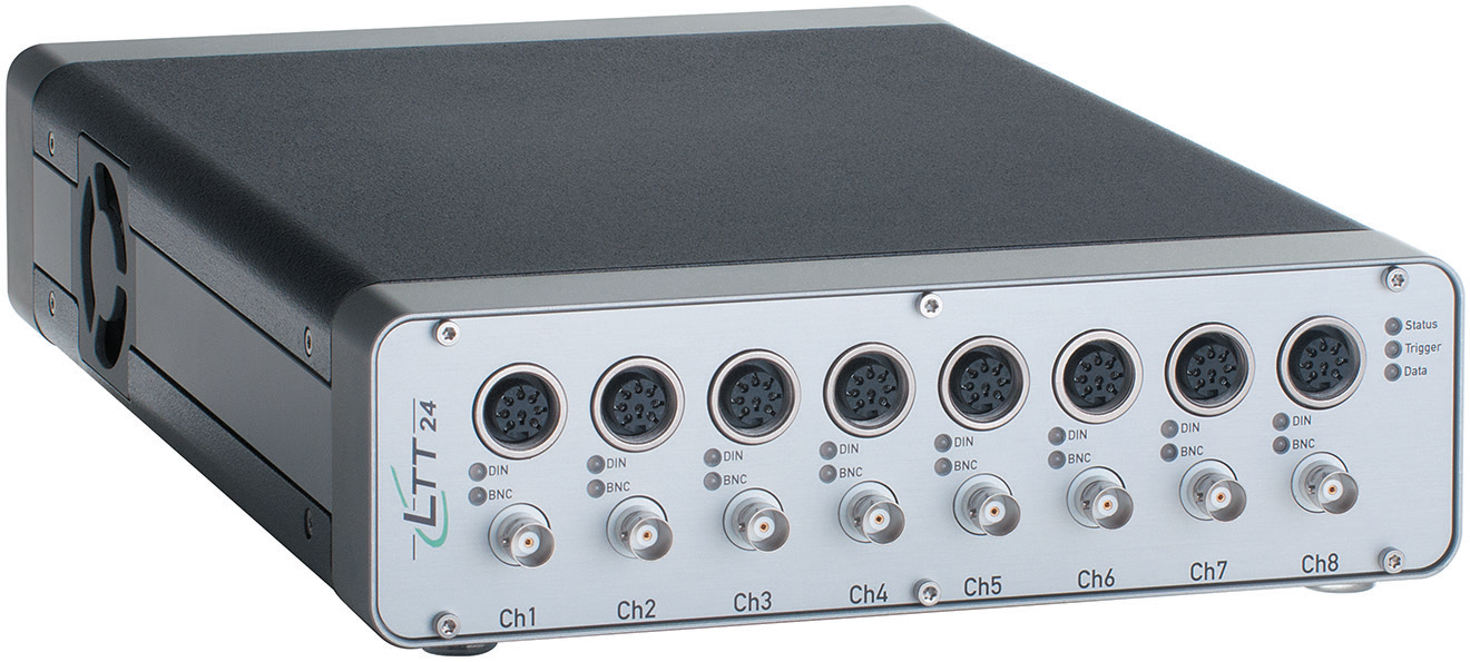
LTT24 Stand-Alone Recorder
The LTT24 measurement system with integrated SSD
As an option, the LTT24 measurement system is also available with a built-in 64GB SSD. (Other SSD sizes on request.)
The system allows uninterrupted recording of measured data with more than 256MByte/s onto the internal SSD.
The 24bit A/D converters generate a data flow of 4Byte per sample with up to 4MSample/s per channel.
This results in a maximum overall sampling rate of 64MSample/s per LTT24 unit.
Using the maximum sampling rate of 4MSample/s (bandwidth DC-1.6MHz), you can record 16 channels for 4 minutes onto the internal 64GByte SSD.
| Recording length on 64GByte SSD |
| Channels |
Sampling rate
[MHz] |
Bandwidth
[DC - kHz] |
Recording length
[min] |
| 16 |
4 |
1600 |
4 |
| 16 |
2 |
800 |
8 |
| 16 |
1 |
400 |
17 |
| 16 |
0,5 |
200 |
34 |
| 16 |
0,25 |
100 |
68 |
| 16 |
0,125 |
50 |
136 |
16 channels with 1MSample/s per channel (or less) can be stored directly and without interruptions on a computer hard disk using a USB 3.0 interface.
This requires a computer and an internal hard disk (SSD) with sufficient performance!